Meshing Overview
Understand what meshing is, what it’s best suited for, and how to best leverage its capabilities.
Introduction
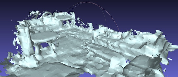
Meshing is a feature of ARDK that provides 3D geometry of the environment created from images, camera poses and, on high end devices, LIDAR depth frames. That 3D geometry is called the Mesh, generated on the fly up to 10 times a second as the user points their device to previously unseen objects. It can be conceptualized as a thin rubber sheet stretching on the surface of every object, without boundaries between ground, wall, furniture, plants, etc.
The input data needed for meshing is automatically captured when enabling the feature when configuring an IARSession. On the first run, the algorithm requires a neural network model to be downloaded. If the required model version already exists on the device, it will load the cached version into memory.
Mesh Usage
The environment mesh enables or expands many AR capabilities.
Visualization : Provide visual feedback as users scan their environment.
Occlusion : Hide virtual objects behind real ones, especially in larger outdoors environments where Depth-based Occlusion may not be practical.
Physics : With the help of
MeshColliders, have virtual objects and characters interact with the environment and real objects.Character Placement and Navigation : As input to the Gameboard
Procedural Object Placement : Populate the AR world with more flexibility than Plane Detection, as illustrated in the Intermediate Tutorial: Meshing Garden Chunks.
Mesh Geometry
The mesh geometry is made up of vertices and faces. Vertices are 3D points; faces are triangles, which are made of three vertices.
In the meshing API, vertices are made of 6 floating point numbers each:
3 for the position of the point (x, y, z);
3 for its normal vector (nx, ny, nz). The normal vector describes the direction the point is facing, which is used for light rendering and collision physics.
The mesh geometry is expressed in the ARDK’s coordinate system convention, which is right-handed and aligned with gravity along the Y-axis. A transformation is needed to comply with Unity’s right-handed coordinate system convention, by flipping the sign of the Y-axis. Helpers like the ARMesh prefab and ARMeshManager take care of that transformation, which most of the time only amount to applying a scale of (1, -1, 1) on the transform of the mesh’s GameObject. See Meshing: Getting Started.
A mesh face is made of 3 integers, each corresponding to a vertex with that index in the list of vertices. These vertex indices are always arranged in a counter-clockwise order, so each face has a known exterior side.
Mesh Blocks
Currently, the meshing API provides mesh information for up to 100 meters (300 feet) around the user. In order to facilitate mesh manipulation, the algorithm slices the world into cubes of the same size (by default 1.4m/55in per side); and groups all its mesh triangles into cubes. Every cube that contains at least one triangle of mesh becomes a mesh block.
Every block is described by four values:
(X, Y, Z) integer block coordinates
vertex count
face count
version number
Block coordinates are integers. Assuming the default block size, (0, 0, 0) is the coordinates of the block containing vertices and triangle between 0.0m and 1.4m on every axis; (-1, -1, -1) is the block containing vertices and triangles between -1.4m and 0.0m on every axis.
For more details, read about the Mesh buffer layout in the Low Level Addendum.
Block and Voxel Size
The default block size of 1.4m (55in) was chosen to be small enough to reduce unnecessary mesh updates in Unity while being large enough to limit the overhead incurred by each mesh object. The desired block size can be configured with the IARWorldTrackingConfiguration.MeshingTargetBlockSize property.
The underlying algorithm models the world in smaller cubes referred to as voxels, and assigns each voxel a probability value for being solid or empty. The resulting mesh is the surface created by separating solid and empty voxels.
The voxel size is fixed and cannot be configured: 2.8cm (1.1in) was chosen as a compromise between noise and precision: bigger voxels cannot capture smaller objects; smaller voxels increase the chances of holes in the mesh and dramatically increase memory requirements.
Block Version and Chunks
Updating Unity Mesh objects is expensive, so each block comes with a version number, which only increases when its vertices or faces change.
This is especially important when the mesh is used for physics, as the computing cost of each ColliderMesh update is significant and grows linearly with the polygon count.
For this reason, applications must absolutely limit the frequency of such updates by:
splitting the overall mesh into smaller sub-meshes with one per block;
only updating the sub-meshes whose block version changed;
(optionally) updating
ColliderMeshes less frequently than theMeshFilterused for rendering by skipping versions.
Unfortunately, each sub-mesh comes with some overhead, so their number must be limited on the application side to a single GameObject per block, instantiated from a prefab called Mesh Chunk. The ARMeshManager helper is provided to manage mesh chunks.
For more details on mesh chunks, read the Mesh Block Prefabs section of the Meshing: Getting Started tutorial.
Session Configuration and LIDAR support
Meshing support is disabled by default for all AR sessions.
On supported devices (see Limitations and Caveats), meshing can be enabled by setting the IARWorldTrackingConfiguration.IsMeshingEnabled flag. Using the ARMeshManager helper class in your scene will configure the AR session automatically.
Sessions configured with IsMeshingEnabled implicitly enable depth estimation, as machine learning-generated depth is a necessary input to the meshing algorithm.
On devices equipped with a LIDAR sensor, such as the iPhone 12 Pro, meshing uses the sensor’s high-fidelity depth data. On such devices, IsMeshingEnabled does not implicitly enable depth estimation. However, it is still possible to explicitly enable depth estimation by setting IARWorldTrackingConfiguration.IsDepthEnabled to true in the session configuration.
When depth estimation is explictly enabled alongside meshing on LIDAR-enabled devices, the mesh is generated by fusing depth data from both sources, as described in the following table:
Meshing enabled |
Depth estimation enabled |
Depth estimation disabled |
|---|---|---|
LIDAR-enabled devices |
LIDAR and depth estimation fused mesh |
LIDAR-based mesh |
Other supported devices |
Depth estimation mesh |
Depth estimation mesh |
Limitations and Caveats
Meshing requires recent devices with 3GB of RAM or more, refer to the System Requirements for a list of supported devices.
To check at runtime if the current devices supports meshing, call the method ARWorldTrackingConfigurationFactory.CheckMeshingSupport().
The mesh quality is best on LIDAR-enabled devices like the iPhone 12 Pro; on other devices, it is dependent on the “computer vision-friendliness” of the environment and can be sorted in three tiers:
Tier 1: Best quality:
Solid, matte, opaque surfaces: wood, bricks, stones, trees, foliage;
Larger non-reflective furniture: couches, tables, shelves;
Highly textured surfaces: carpets, murals, wallpapers, curtains.
Tier 2: Good quality in well lit environments:
Plain color surfaces: painted surfaces, white walls, raw concrete;
Fine-texture surfaces: sand, stone, grass, asphalt.
Smaller furniture: chairs, benches.
Tier 3: Poor quality:
Transparent surfaces: glass, windows, water;
Semi-transparent surfaces: stained glass, shades;
Reflective surfaces: polished granite, metals, varnished wood, screens, mirrors;
Thin objects: lamp posts, fences, bicycles;
Dark environments: dawn, dusk, night, low-light indoors;
Moving objects: people, pets, vehicles, foliage in the wind.
Poor quality typically manifests itself with the following differences between mesh and reality:
Inaccuracies, offset between the mesh and the real surface;
Noise, rugged mesh on smooth surfaces;
Artifacts, pieces of mesh floating in mid air;
Holes, areas where the mesh is not airtight;
Incomplete, missing objects.
Tutorials
To start using meshing, read the Meshing: Getting Started tutorial first and then pick one of the advanced tutorials depending on the type of experience you wish to build.
Beginner Tutorial: Meshing Getting Started - Learn how to add meshing to your AR experience.
Intermediate Tutorial: Meshing and Collisions - Learn how to use meshing and collide objects with the generated mesh.
Intermediate Tutorial: Meshing Garden Chunks - Use generated meshes to create an AR garden.
Intermediate Tutorial: Meshes in the Unity Editor - Learn how to save generated meshes on the device and extract them into Unity.
Advanced Tutorial: Gameboard - Use Gameboard to query the environment for object placement, procedural gameplay and character navigation.