Generating Depth Data
Take advantage of depth maps to create immersive AR experiences.
Overview
With the current state of technology, you can track the position of the camera in a scene and detect planar surfaces, even on an average mobile device. For example, you can place a virtual character on an open surface in the real world and take a photo of it.
A much more interesting AR experience, however, could involve the virtual character interacting with the real world instead of just standing in it. Understanding scene depth unlocks a whole host of features: occlusions, navigation, collision, depth of field effects and more.
ARDK’s depth outputs are generated by feeding color image input into a deep learning algorithm. That means:
Depth-based features can run on a wider range of devices rather than just those with depth sensors, although sensors will be utilized if available.
The depth algorithm works in both indoor and outdoor environments, on the scale of buildings, and at a higher range of distances (0.2m to 100m).
The depth algorithm requires minimal initial camera motion to output results, and responds immediately to moving objects.
Depth is output for all objects instead of just a subset (e.g. people).
This page covers how to enable depth estimation, access raw depth data, and some considerations to keep in mind to optimize the accuracy of the estimations. ARDK provides a few classes that can be dropped into a Unity scene to quickly add depth-based effects (occlusions) to your experience.
Enabling Depth Estimation
To enable depth estimation:
Check whether the device is able to support depth estimation. The full list of supported devices is available on ARDK’s System Requirements page.
using Niantic.ARDK.AR.Configuration;

var isSupported = ARWorldTrackingConfigurationFactory.CheckDepthEstimationSupport();
The value returned here is only a recommendation. Depth estimation will run on non-supported devices, but with degraded performance, accuracy, and stability levels.
Configure and run an ARSession to start generating data.
void RunWithDepth(IARSession arSession)
{
  var config = ARWorldTrackingConfigurationFactory.Create();

  // Enabling IsDepthEnabled is required to generate raw depth estimation data.
  config.IsDepthEnabled = true;

  // Default/recommended value is 20 to balance resource consumption with performance.
  config.DepthTargetFrameRate = 20;

  arSession.Run(config);
}
Use DepthTargetFrameRate to set the framerate the session aims to update estimations at. Raising this value will allow for more frequent updates but also cause a nontrivial performance loss (inferring depth is an expensive operation). A target of 20fps is recommended as a starting point; tweak the value to fit your application’s requirements.
Accessing Depth Data
Depth data is provided through the IARFrame.Depth property. Get the most recent frame either through IARSession.CurrentFrame property, or by subscribing to the IARSession.FrameUpdated event.
A few things to keep in mind when using depth data:
An ARFrame’s
Depthvalue will at times be null, like while the algorithm is starting up, or when AR updates come in faster than depth estimation updates.An ARFrame’s depth buffer also lags a few frames behind the camera image used to generate that buffer. Therefore, always Interpolate the depth using the given frame’s ARCamera in order to get the best depth estimation for the given frame.
An ARFrame’s depth buffer doesn’t necessarily align with the screen. The ARDK provides methods to get both the unaligned buffer as well as a buffer aligned and cropped to the screen, as described in Aspect Ratio below.
Creating a Disparity Texture
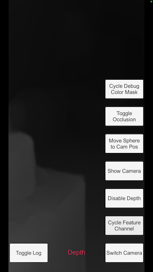
The raw values in the Depth.Data buffer are floats each representing a pixel’s depth in meters in the range of NearDistance to the FarDistance. If you just want to see the depth buffer rendered to the screen for debugging purposes, you can enable ToggleDebugVisualization on your ARDepthManager. For example you might toggle this in the Start() method of your script:
using Niantic.ARDK.Extensions;

public ARDepthManager _depthManager;

void Start()
{
    // Enable debug visualization of depth buffer
    _depthManager.ToggleDebugVisualization(true);
}
If you need a texture representation of the depth buffer to modify or otherwise use for custom screen output, you can create a disparity texture with normalized values ranging from 0 (far objects) to 1 (near objects) by calling the CreateOrUpdateTextureRFloat method. Alternatively you can create a RGB texture from the depth buffer by calling CreateOrUpdateTextureARGB32, however you’ll need to provide your own normalization function:
Texture2D _disparityTexture;

void UpdateDisparityTexture(IDepthBuffer depth)
{
  float maxDisp = 1 / depth.NearDistance;
  float minDisp = 1 / depth.FarDistance;

  depth.CreateOrUpdateTextureARGB32
  (
    ref _disparityTexture,
    FilterMode.Point,
    depth => (1/depth - minDisp) / (maxDisp - minDisp)
  );
}
See Intermediate Tutorial: Depth Textures for an example that gets the depth buffer and renders it to screen using a shader.
Note that these methods return the raw buffer data that hasn’t been cropped or aligned to the screen. See the next section for how to deal with this.
Aspect Ratio
The aspect ratio and resolution of the depth buffer will not necessarily match that of the device camera or screen (those values are determined by the underlying deep-learning model). You can use CopyToAlignedTextureARGB32 or CopyToAlignedTextureRFloat to get a depth texture aligned with the correct dimensions and aspect ratio of the given camera. These methods do a per-pixel sampling process, so they can be slow. Alternatively, get the SamplerTransform from the AwarenessBufferProcessor and use this in a custom shader to apply the cropping and alignment in a single pass. See “Aligning Awareness Buffers with the Screen” in Rendering in ARDK for more details.
The alignment process may result in cropping. Cropping will always lead to data being cut off in the horizontal directions. Instead of cropping vertically, ARDK will instead add blank space to the right and left in order to avoid losing data, as seen in the screenshot below. A simple shader is being used to color pixels based on their depth, and there are black columns on the side edges because no depth data is available in those regions.
Using ARDepthManager
To simplify the process of enabling and accessing depth data, we provide a Manager you can add to your scene. The API reference and in-code comments/tool tips for ARDepthManager explains how to use it.
Depth Information and the Rendering Pipeline
In addition to rendering camera feed data, the ARDK render pipeline is responsible for generating z-buffer data if the session is configured to generate depth information. For this reason, if you enable depth generation in your scene, either through use of an ARDepthManager or configuring the ARSession for IsDepthEnabled, you must make sure you have a ARRenderingManager in your scene. If you use ARDepthManager, the ARDepthManager component must be added to the same object that the ARRenderingManager is added to.
Depth Information and Mock Mode
If you want to access depth data in the Unity Editor, you can use Mock mode. You can use one of several pre-made mock environments available in the ARDK Mock Environments package available on the ARDK Downloads page. Import the Mock Environments package into your scene, then in the ARDK > Virtual Studio window, under the Mock tab, select the prefab you want to use from the Mock Scene dropdown.
When you run in Unity play mode, mock mode will automatically instantiate the prefab and gather depth data on the prefab meshes, if your ARSession has depth enabled.
If none of the pre-made environments meet your needs, you can create your own mock environment. Create a mock AR environment by adding a prefab to your project with the mock environment geometry, along with a MockSceneConfiguration component on the root GameObject in the prefab. You can then choose your prefab in the Mock Scene dropdown.
Troubleshooting: Model Quality Considerations
ARDK’s depth data is approximated through machine learning, meaning it can run on devices without specialized depth sensors but also that its output is inherently both noisy and biased.
This GIF illustrates what noise and bias can result in. The sphere is static, sitting just above the wood floor in world-space, but the depth algorithm thinks the floor should occlude very differently depending on viewing angle and even drastically from frame to frame.
To make optimal use of depth features, you will need to design your experience around these points:
Depth maps have a significantly lower resolution than the camera image, and are upsampled.
Depth maps suffer from temporal inconsistency, or “jitter”. Sometimes jitter occurs even when the camera is not moving and the scene is not changing. This is a known problem with neural networks which predict on single frames. Stability tends to worsen as objects get closer than the model’s minimum extent, most notably if the user looks at the ground near their feet.
It’s therefore not recommended to rely on either a single frame’s or a single pixel’s depth output.
The current model specializes in estimating horizontal depths for objects at eye-level, so they may not perceive the ground as entirely flat and also aren’t well-suited to estimating vertical depths. This means depth estimation will generally be more accurate if the camera is facing towards the horizon as opposed to more upwards or downwards.
Depth maps are sensitive to color changes, including mild lighting differences. This is a major factor in noise generation.
Depth edges are not perfectly aligned to object edges, so the depths might be wider/blobbier than in reality.
Models must be downloaded over the internet (assuming it isn’t cached locally) before depth estimations can run.